All information regarding my MikroTik’s configuration – off-bridge management port, VLANs, custom firewall rules, Pi-hole, mDNS, and more!
Starting a networking noob, I go step-by-step into the MikroTik world as I setup my hardware; it’s the walk-through I wish I’d had when I started.
From zero to slightly-above-zero
I don’t know jack about networking.
Not in the same way I don’t know jack about 7th century agricultural practices1, but my router feels (felt!) like a benevolent box providing internet access, with my ISP’s blessing.
I didn’t like that situation. I expect to have to interact with the internet continuously, so I figured spending hours learning (some) of it would pay dividends. After some online search, I stumbled upon a Lithuanian company called MikroTik which seemed known to require actual knowledge of what you were doing, and were supporting old hardware. So I dived in and got the hAP ax2.
MikroTik hAP ax2 | A beast in disguise.
Disclaimer
I am a networking noob. I learnt a ton, but am far from a reference. This is not a guide. If you think you know more about networking than me, you very likely do. I’m more the lost sheep than the sheperd.
Regardless, this guide would’ve been helpful to me during these troubleshooting hours, and might be helpful to future me (and who knows, others) to understand what I did.
I spend time defining words that might seem obvious to others; they’re words I’d have loved to have seen clearly defined diving in.
Initial connection to the router
On first boot, our MikroTik router runs the default configuration, along with default credentials.
We get access to our router by hooking an ethernet cable from our computer to the MikroTik’s ether5 port.
We won’t have internet yet – and that’s fine.
ether-whatport ?
When I say etherXport, I mean the X-th physical ethernet port – the actual hole – on my router.
That is the standard way to refer to these physical ports, from what I’ve seen.
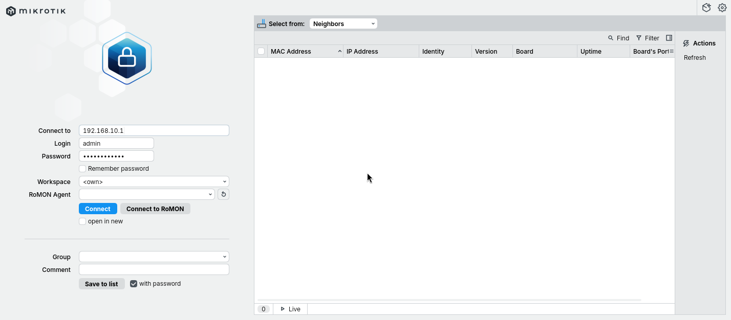
To start configuring it, we install MikroTik’s GUI – WinBox.2
Upon launching it, we enters our router’s default credentials, and tada!, a brand new default-configuration router.
Where can I find my router’s default credentials?
The router’s default IP, username and password can be found under the router, on a sticker.
⚠️ Do not forget to change the default credentials on first login. ⚠️
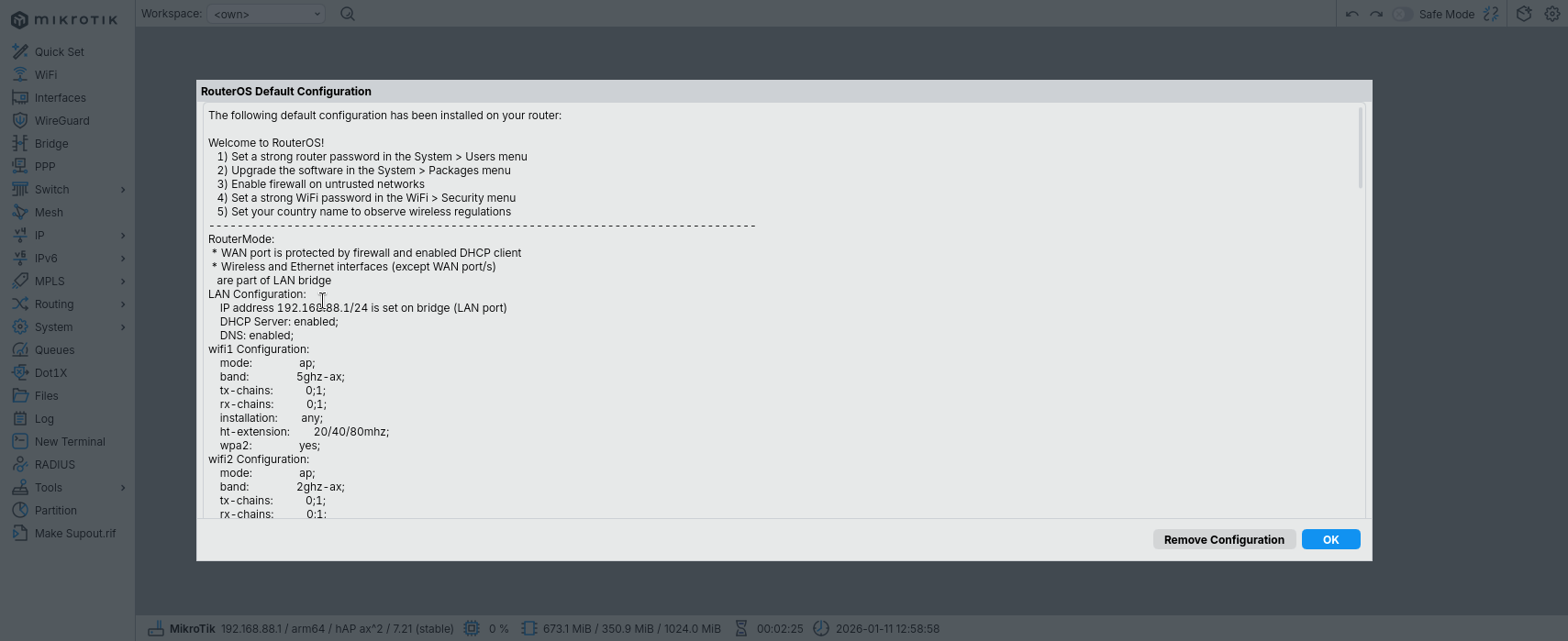
WinBox | MikroTik's GUI WinBox's first login
Once logged in, we get a warm welcome from MikroTik, and a friendly reminder to change our router’s credentials.3
WinBox is a GUI, which really mimicks how MikroTik’s CLI is built. Everything can be done via CLI, some things via GUI.
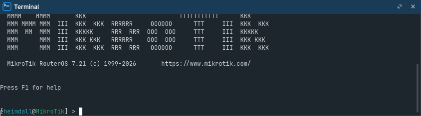
I encourage you to do most – if not all – operations via CLI, as it helps knowing what’s actually happening. To open an instance of that CLI, click on New Terminal on WinBox’s left sidebar.
WinBox's CLI
We can then change our router’s credentials:
Create a new user
# Create a new read&write access user/useraddname=SOMEUSER group=full password=SOMEPASSWORD
Log off WinBox, and log back in as our newly-created user
Disable the admin user, since we won’t need it anymore
# Disable admin user/userdisable admin
We now have a working router, in a default state that’s not bad not great.
We will start off this default configuration, applying changes incrementally, as I explain what I’m doing and why I’m doing it.
Not how it happened
This entire post is far from how I got this final config, as I had to learn plenty of networking stuff along the way.
This is more of a “This is how I’d do it now, and how I’d have liked to see it done then” situation.
I reconfigured my router from scratch to make sure the steps were working as intended, but it’s entirely possible mistakes sneaked in.
If so, sorry.
Basic concepts to know before starting
Throughout this post, I’ll properly define concepts which I refer to, and are – from what I saw – very often loosely-used, so that we can build upon these concepts as we progress throughout our networking journey. Below are the first building blocks. They might be obvious, but I’d rather define them clearly rather than assume you know them – especially because I sometimes thought I understood them, but I didn’t.
This includes my computer, my phone, my smart fridge, the MikroTik router itself, as well as Google’s servers in the US.
What is a network?
A network is a set of links through which hosts talk to each other.
To “join” a network means to “plug into” (so to speak) this set of links, as if you were “joining” a group conversation.
What is an interface?
An interface is the point of connection between a host and a network (hence the name).
They are software constructs, meaning they don’t refer to the actual hardware (i.e. what we called “ether5 port” before).
Physical interface: An interface that is bound one-to-one to actual hardware.
e.g. in the router’s software, there is an ether5 interface bound to the ether5 port
Virtual interface: An interface that is not bound 1:1 to actual hardware.
It acts as the “door” through which the host talks to the network, relying on physical interfaces to do so.
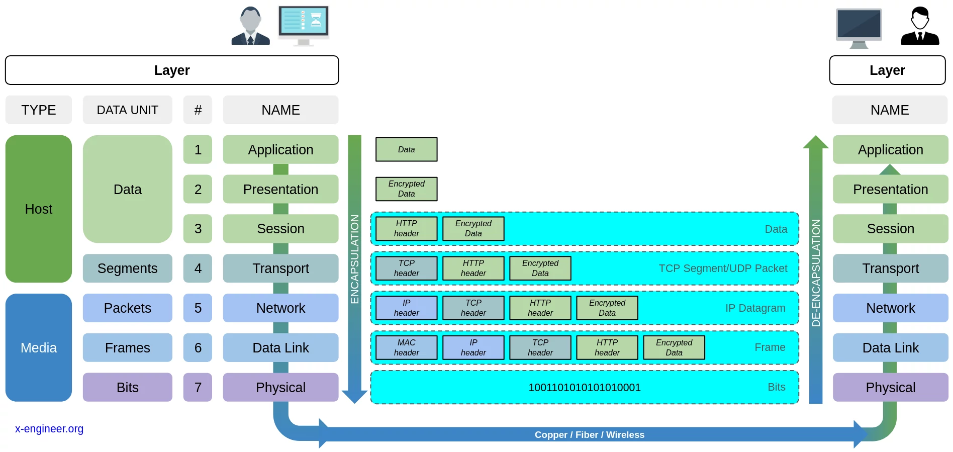
What is the OSI model?
The Open Systems Interconnection (OSI) model is a conceptual framework standardizing how data moves from one host to another over a network. It describes how a host should “pack” (i.e. encapsulate) data so that it can be sent over a network, and how the receiving host should “unpack” (i.e. decapsulate) that data.
This “how to pack up data before transmitting it“-process consists of 7 distinct consecutive steps – called Layers. That is, when a host sends data (e.g. an email), it first encapsulates that data by moving down the layers (from layer 7 to layer 1). And any host receiving that data decapsulates it by moving up the layers (from layer 1 to layer 7).
This layered approach allows us to separate concerns. In the end, each layer has its own responsibilities (e.g. ensuring data is correctly moved across networks), data units (e.g. Layer 3 deals with packets) and instruction on how to transform the data for the above layer (i.e. decapsulate) and for the below layer (i.e. encapsulate).
Responsible for sending/receiving raw bit streams over a physical medium, like copper wires or wireless signals.
What is a router? And a switch?
A router is a device whose job is to route packets to the right destination, possibly across networks.
A switch is a device whose job is to forward frames to the right destination, within a single local network.
Nowadays, ISPs often sell/lease us hardware they call “routers”, and so we call them “routers”, but they’re not.
They’re a router/switch/bridge/gateway/etc in one box. In this guide, we’ll call the hAP ax2 a router, even though it’s more than that.
Main features
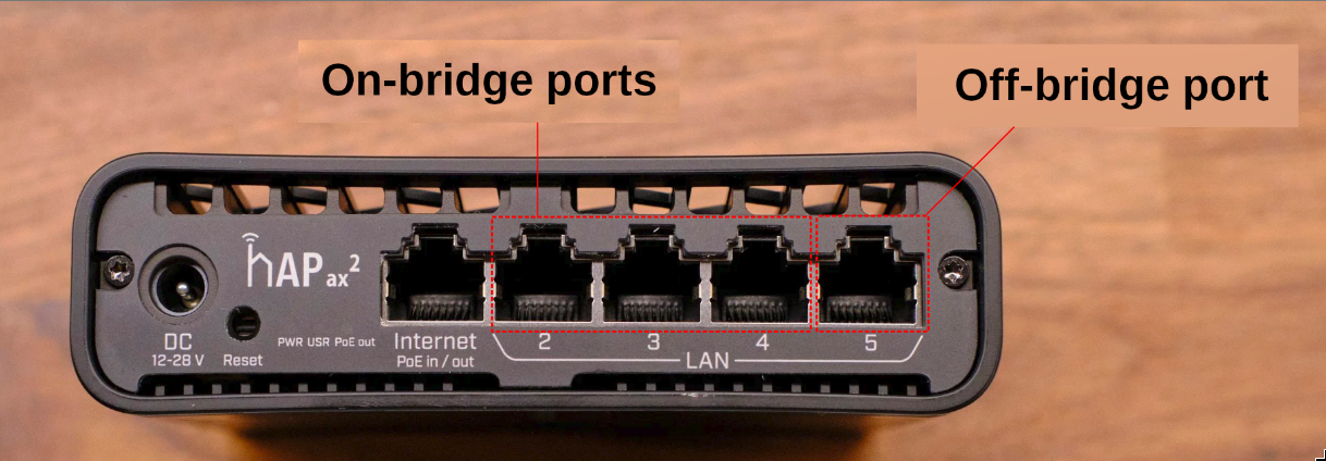
Off-bridge Management Port
On-bridge and off-bridge ports
One ethernet port will be dedicated to router-management. That is, its only purpose will be to give us admin-access to our router were we to ever get locked out.4
This port will be off-bridge, so that it stays unaffected by any bridge-related setting change we might make in the future. In that sense, it’s a set-and-forget open-door into our router. The downside is anyone with physical access to our router gets admin access; that is a risk I am willing to take.
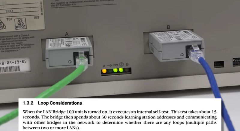
In short, all interfaces within a broadcast domain “see” each-other. Nowadays, that thing is almost-always a software construct, but back in the old days you could buy bridges. They were a physical box with two physical holes (ports) that would bridge two networks together.
Backside-view of the DEC Bridge 100 from 1986, one of the first bridges
By default, MikroTik routers bridge ether2 through ether5 (along with the WiFi interfaces). By this I mean that in the default MikroTik configuration, there is a bit of code called bridge. And “on” that bridge are interfaces ether2 through ether5. Since they’re on that bridge, these interfaces share the same broadcast domain.
An off-bridge interface is hence an interface that is not on the bridge.
What is broadcast domain?
A broadcast domain is subset of a network in which all hosts can reach each other by broadcasting at the Data Link Layer (Layer 2).
That is, they don’t have to move one layer up – i.e. to the Network Layer (Layer 3).
To turn ether5 into a management port:
Add the ether5 interface to a management-dedicated interface list.
# Rename my ether5 interface, for good measure/interface ethernetset[finddefault-name=ether5 ]name=ether5-mgmt
# Create an interface list dedicated to management interfaces/interface listaddname=MGMT
# Add my newly-renamed interface to it/interface list memberaddinterface=ether5-mgmt list=MGMT
Our router – which is a host – will own several interfaces – virtual and physical.
To facilitate assigning rules to them – especially once we start messing with the firewall –, we’ll add them to an interface lists.
This allows use to say – e.g. – “ether5-mgmt belongs to MGMT interface list, and any MGMT inferface can manage the router.
Create a DHCP service for this management interface.
# Define a static-like IP pool for it, containing only one usable IP (.2)/ip pooladdname=pool-ether5-mgmt ranges=192.168.55.2# Initialize its DHCP service, using the only-one-usable-IP-in-it pool/ip dhcp-serveraddaddress-pool=pool-ether5-mgmt interface=ether5-mgmt name=dhcp-ether5-mgmt
# Define the DHCP's handshake details /ip dhcp-server networkaddaddress=192.168.55.0/30dns-server=192.168.55.1gateway=192.168.55.1# Set this subnet's default gateway to .1/ip addressaddaddress=192.168.55.1/30interface=ether5-mgmt network=192.168.55.0
Because we isolated ether5-mgmt from the bridge, it no longer has access to the main network’s DHCP server. By spinning up a dedicated DHCP service just for this port, you can plug your laptop directly into ether5 and instantly get an IP address without having to manually configure your laptop’s network settings.
What is DNS?
The Domain Name System (DNS) is a service whose job is to convert domain names (e.g. google.com) into actual IP addresses (e.g. 172.217.208.102).
Allow MGMT interfaces to talk to the router.
/ip firewall filter# Allow MGMT interfaces to talk to the routeraddaction=accept chain=input comment="MGMT -> router: ACCEPT"in-interface-list=MGMT
# Move that rule above the default "not LAN cannot talk to the router" rulemove[findcomment="MGMT -> router: ACCEPT"][findcomment="defconf: drop all not coming from LAN"]
What are firewall rules? And chain?
A firewall is responsible for evaluating each packet entering (or exiting) an interface against a list of rules.
These rules are applied sequentially, and each consists of a matcher (a criteria, e.g. source IP or destination port) and an action (i.e. what to do with the packet, e.g. dropping it or letting it through).
But what packet is subject to what firewall?
This depends on the path taken by the packet, also called chains.
The basic and most commons chains are:
input chain: Traffic destined for the router itself (e.g. accessing the WinBox GUI).
forward chain: Traffic passing through the router (e.g. accessing the internet, pinging another host).
output chain: Traffic generated by the router itself.
Take ether5-mgmt interface off the bridge.
# Take ether5-mgmt off the bridge/interface bridge portremove[findinterface=ether5-mgmt]
Kicked out? Get used to it.
Since we just moved ether5-mgmt off the bridge, and since we’re currently plugged into it, it kicked us out because we had the “bridge-given” private IP.
That’s normal and expected, no need to panic. Just continue following this guide.
Ensure it worked
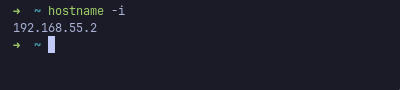
By unplugging-replugging the ethernet cable into our computer’s ethernet port, our computer will ask for the a new private IP – to our freshly-set-up DHCP service – and will receive the only IP that the ether5-mgmt-bound DHCP can hand out: 192.168.55.2 (the other one – 192.168.55.1 – being reserved for the router).
Confirming that we were assigned the expected private IP.
You should then be able to log back in WinBox – after unplugging-replugging the RJ45 cable –, this time on the 192.168.55.1 IP.
If it doesn’t work, no worries! You can plug into any of the other still-on-the-bridge ports – ether2, ether3 or ether4, and get back in the router to figure out what went wrong.
Now that our dedicated management port is set up, let’s plug our computer into the ether2 port (and log-out-then-log-in-through-winbox) to further configure our router. We do this because ether5-mgmt is only meant for router-management, and hence won’t have internet access.
Get internet
Currently, we have no internet, as we’d expect.
To get internet, we
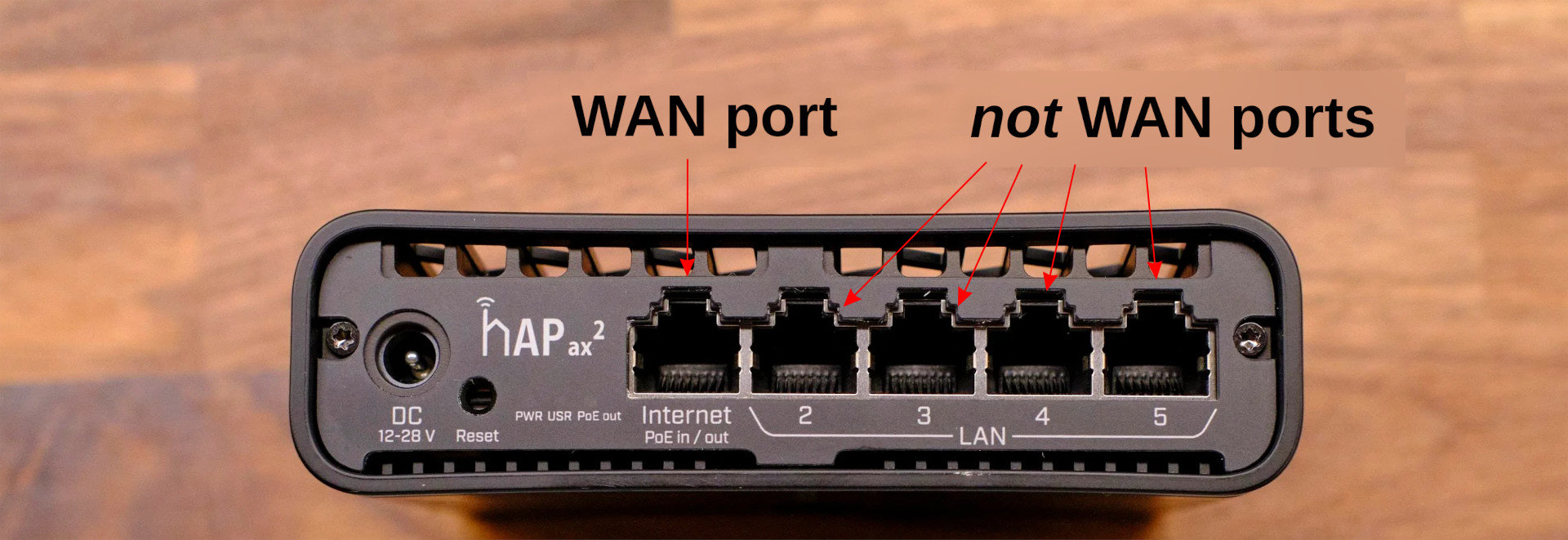
Plug our internet-giving-device5 into our router’s dedicated WAN port, i.e. ether1.
Whereas your LAN is Local, the WAN is essentially other hosts (i.e. computers/servers) on what is usually called “the internet”.
Routers will usually have a single ethernet port dedicated to “establishing communication with the bigger-network-outside”. That port is called the WAN port, and is basically your door through which your router accesses the internet.
And tada !, internet!
As per MikroTik’s default firewall rules – and since we’re on ether2, which is part of the LAN interface list, we can access the WAN.
Ensure it worked
To make sure it worked, open any webpage. If it loads, you’re good to go.
If not, plug your computer back into ether5 port and log into the router to troubleshoot it.
Stricter firewall rules
The default firewall rules are fine, but I’d rather take a default deny approach, where anything that is not explicitely allowed gets dropped.
As we later add rules, it’ll provides us with a safety net in case I mess up, and forces me to be very intentional in setting up this firewall.
For a default-deny firewall:
Prepare the disabled default-deny rules.
# Drop all input-chain packets/ip firewall filteraddaction=drop chain=input comment="any -> router: DROP"disabled=yes# Move the drop-all input-chain packets at the end of the input chain rulesmove[findcomment="any -> router: DROP"][findcomment="defconf: drop all not coming from LAN"]# Drop all forward-chain packets addaction=drop chain=forward comment="any -> any: DROP"disabled=yes# Move the drop-all forward-chain packets at the end of the forward chain rulesmove[findcomment="any -> any: DROP"][findcomment="defconf: drop all from WAN not DSTNATed"]
Note that these rules are currently disabled; we’ll enable them once we’re ready.
Also note that we place these rules above the default-“drop-what’s-unwanted” rules, just in case.
Allow LAN interfaces to talk to the router.
# Allow LAN -> router communications/ip firewall filteraddaction=accept chain=input comment="LAN -> router: ACCEPT"in-interface-list=LAN
# Move this rule so it's before out default-deny rulemove[findcomment="LAN -> router: ACCEPT"][findcomment="any -> router: DROP"]
This rule is currently redundant, since no drop rules currently prevents us from doing so.
This will change soon, so let’s avoid cutting us off our newly-acquired internet.
Allow LAN interfaces to talk to WAN interfaces.
# Allow LAN -> WAN communications/ip firewall filteraddaction=accept chain=forward comment="LAN -> WAN: ACCEPT"in-interface-list=LAN out-interface-list=WAN
# Move this rule so it's before out default-deny rulemove[findcomment="LAN -> WAN: ACCEPT"][findcomment="any -> any: DROP"]
Same as above: for now we can, so let’s make sure it stays that way with a default-deny approach.
Enable the default-deny rules on the input and forward chain.
Currently being on ether2, i.e. a LAN interface, you should still have internet access, and still be able to manage the router (i.e. connect to it via WinBox).
If not, plug your computer back into ether5 port and log into the router to troubleshoot it.
VLANs
I wanted to segregate my devices into groups, and limit interactions between these groups.
Virtual Local Area Networks (VLANs) are the perfect tool for that.
Normally, frames are just a bunch of bytes getting routed by a router.
When an ethernet frame enters a VLAN-aware environment – e.g. our router –, the router “brands” – i.e. tags – that frame with some ID – i.e. a VLAN ID.
The router then makes sure that that ethernet frame only ever travels to interfaces allowed to see that specific ID.
Right before leaving the device, the router strips the tag off the ethernet frame.
What is a frame?
At Layer 2 – the Data Link layer in the OSI model – the fundamental unit of data is called a frame.
If we’re on an Ethernet physical link (i.e. our data goes through an RJ45 cable), then we’re working with the Ethernet protocole, then these frames are Ethernet frame.
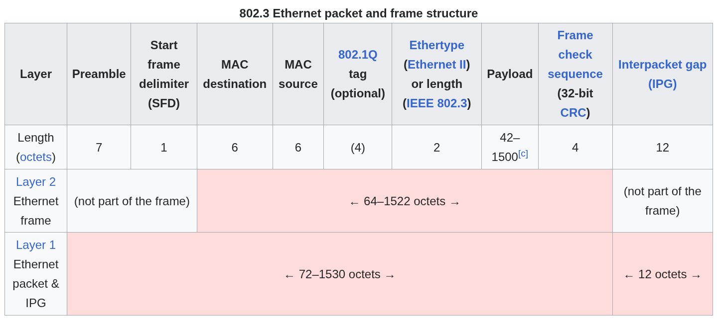
It’s basically a bunch of bytes in a highly-agreed-upon order, as defined by the IEEE 802.3. Standard. Within these bytes, 4 of them can be used for the VLAN tag of that frame. A full frame looks like that:
An Ethernet frame, as defined by the IEEE 802.3. Standard. Can you spot where the VLAN ID goes?
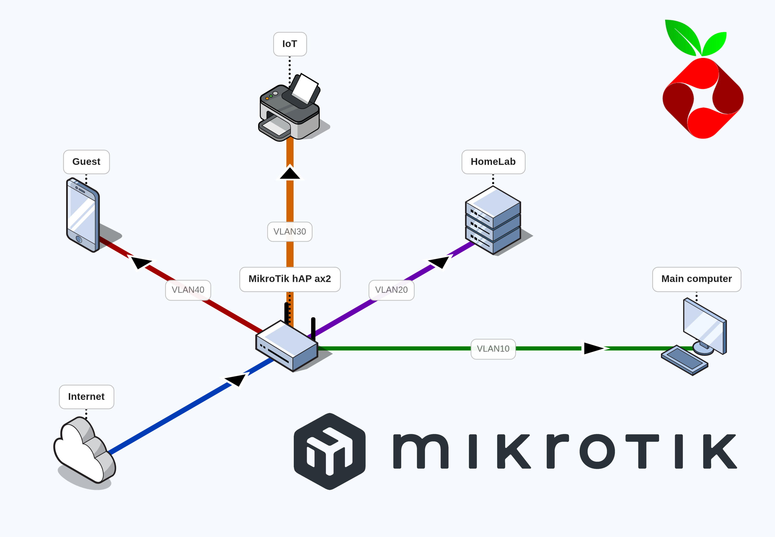
Each group would get its own VLAN – and hence associated VLAN ID –, and we’ll figure out custom firewall rules afterwards. In my usecase, I distinguished 4 groups, from high-trust to low-trust:
Description
Trust Level
VLAN ID
VLAN Name
My main computer and only the most trusted hardware.
High
10
vlan10-main
My homelab, and other server-like devices.
Medium
20
vlan20-homelab
My IoT, like connected lightbulbs, 3D printers and vacuum robots.
Low
30
vlan30-iot
Any guests coming over.
Low
40
vlan40-guest
To setup these 4 VLANs:
Configure the 4 VLANs, so they’re ready for use.
# Create 4 VLANs/interface vlanaddinterface=bridge name=vlan10-main vlan-id=10addinterface=bridge name=vlan20-homelab vlan-id=20addinterface=bridge name=vlan30-iot vlan-id=30addinterface=bridge name=vlan40-guest vlan-id=40# Add all VLANs to LAN list/interface list memberaddinterface=vlan10-main list=LAN
addinterface=vlan20-homelab list=LAN
addinterface=vlan30-iot list=LAN
addinterface=vlan40-guest list=LAN
# Define IP pools for each VLAN/ip pooladdname=pool-main ranges=192.168.10.10-192.168.10.254addname=pool-homelab ranges=192.168.20.10-192.168.20.254addname=pool-iot ranges=192.168.30.10-192.168.30.254addname=pool-guest ranges=192.168.40.10-192.168.40.254# Initialize each VLAN's DHCP service, using the just-now-defined IP pools/ip dhcp-serveraddaddress-pool=pool-main interface=vlan10-main name=dhcp-main
addaddress-pool=pool-homelab interface=vlan20-homelab name=dhcp-homelab
addaddress-pool=pool-iot interface=vlan30-iot name=dhcp-iot
addaddress-pool=pool-guest interface=vlan40-guest name=dhcp-guest
# Define each DHCP's handshake details /ip dhcp-server networkaddaddress=192.168.10.0/24dns-server=192.168.10.1gateway=192.168.10.1addaddress=192.168.20.0/24dns-server=192.168.20.1gateway=192.168.20.1addaddress=192.168.30.0/24dns-server=192.168.30.1gateway=192.168.30.1addaddress=192.168.40.0/24dns-server=192.168.40.1gateway=192.168.40.1# Set each subnet's default gateway to .1/ip addressaddaddress=192.168.10.1/24interface=vlan10-main network=192.168.10.0addaddress=192.168.20.1/24interface=vlan20-homelab network=192.168.20.0addaddress=192.168.30.1/24interface=vlan30-iot network=192.168.30.0addaddress=192.168.40.1/24interface=vlan40-guest network=192.168.40.0
Have all physical ports apply VLAN 10 (except our previously-set-aside ether5).
The PVID (Port VLAN ID) is a setting telling the bridge to tag any ethernet frame entering it via a given interface.
Why is it called a port then? Because an interface connecting to a bridge makes a port.
Hence, it’s data going through that port that gets tagged.
This bridge port is not to be confused with a physical port, such as ether2.
What is frame-types?
A port – i.e. the link between an interface and a bridge – sees frames going through it.
A port’s frame-types parameter allows us to only allow certain frames to go through that port.
This parameter can take 3 values
admit-all: All frames go through.
admit-only-vlan-tagged: Only frames already-carrying a VLAN tag go through. This would be use if e.g. another device was responsible for tagging the frames.
admit-only-untagged-and-priority-tagged: Only frames that do not carry a VLAN tag can go through. This prevents a potential attacker from pre-tagging frames (called VLAN hopping). Additionally, frames carrying a priority tag are allowed to go through.
But what is a priority tag you ask? A priority-tagged frame is a frame tagged with VLAN ID 0 but carrying Quality of Service (QoS) information. That information is held within the 4 bytes reserved for the VLAN tagging (as per the IEEE 802.1Q standard), and communicates how “urgent” the handling of that frame is. This mechanism allows router to prioritize low-latency-needing frames (e.g. video calls) over I-don’t-care-as-much-about-latency frames (e.g. file download).
Activate VLAN-filtering on the bridge.
# Enable VLAN-filtering on the bridge/interface bridgeset[findname=bridge ]vlan-filtering=yes
We just setup 4 VLANs as virtual interfaces on our bridge. By activating VLAN-filtering, we tell the bridge to become VLAN-aware – which it was not until now. This VLAN-aware bridge will now care about all these pvid and admit-only-untagged-and-priority-tagged settings we gave it.
Kicked out? Hi again.
Since we were on a non-VLAN connection – through the ether2 interface – and just activated VLAN-filtering, the router kicked us out. That’s expected, so no need to panick.
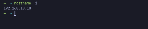
Confirming our newly-acquired private IP is as expected in the 192.168.10.x range.
After unplugging and replugging the ethernet cable into our computer, we should receive a new private IP, this time in the 192.168.10.x. From there, we should be able to log back into WinBox, but this time on 192.168.10.1.
Clean-up leftover config, from back when we didn’t use VLANs.
# Remove the default-pool, since each interface has its own now/ip poolremove[findname=default-dhcp]# Remove the default-DHCP-server, since each interface has its own now/ip dhcp-serverremove[findinterface=bridge]# Remove the default-network, since each interface has its own now/ip dhcp-server networkremove[findaddress="192.168.88.0/24"]# Remove the default-gateway, since each interface has its own now/ip addressremove[findinterface=bridge]
Ensure it worked
After unplugging and replugging the ethernet cable into our computer, we should receive a new private IP, this time in the 192.168.10.x. From there, we should be able to log back into WinBox, but this time on 192.168.10.1.
If not, something went wrong, but thanks to our dedicated management port, you can connect back to our router via ether5.
WiFi
Wired connection is nice. Wireless is (sometimes) better.
My router can act as an Access Point, with its two WiFi radios. Each radio supports a specific WiFi frequency. To avoid crowding my airwaves6. I will set up my WiFi interfaces so that my low-bandwidth devices (IoT & guests) stay on the 2.4GHz-radio, leaving the faster 5GHz-radio clear for my main devices. Also, I want one network per VLAN. Hence we have:
main & homelab VLANs are on both 2.4GHz and 5GHz, since they need access to both
iot & guest VLANs are only on 2.4GHz, as they won’t really suffer from slower speeds
What is an Access Point? A radio?
An Access Point (AP) is a device allowing other WiFi-enabled devices to connect to a network. In our case, the router acts as an AP.
That AP contains antennas – i.e. physical pieces of metal meant to enable reading electro-magnetic signals.
These fancy pieces of metal are leveraged by two physical chips in the AP, called radios. One chip handles 5GHz communications, while the other 2.4GHz. Each radio has one interface, representing that radio in software.
By default, the 5GHz-chip is bound to the wifi1 interface, and the 2.4GHz-chip to wifi2. Since they’re bound-to-a-physical-radio interfaces, they’re called physical interfaces.
A physical interface can then spawn virtual interfaces, which inherit the physical property of their (physical) parent interface. This allows use to have several WiFi networks off a single radio.
To create 4 WiFi’s, one per VLAN:
Create reusable WiFi configuration profiles, one per interface.
Setup my main WiFi network off both physical interfaces.
# Unset default WiFi configurations, # as they will clash with our newly-created reusable configurations /interface wifiunset[find default-name~"wifi"] configuration.ssid
unset[find default-name~"wifi"] security.passphrase
# Apply our configurationset[find default-name~"wifi"]configuration=cfg-main
# Set 2.4GHz radio to transmit on a narrow widthset[finddefault-name=wifi2 ] channel.width=20mhz
Make sure you unset the default configurations, as they will have precedence over our newly-applied configuration profile.
We are setting the 2.4GHz radio to use a 20MHz channel width, i.e. it’s allowed to transmit within 20MHz of its center frequency.
We pick this width for stability and low interferences, as others have highlighted.
Spawn 4 virtual interfaces for the homelab, iot and guest networks.
# Create a virtual interface off the 5GHz-physical-interface, for the Homelab/interface wifiaddconfiguration=cfg-homelab disabled=nomaster-interface=wifi1 name=wifi1-homelab
# Create 3 virtual interfaces off the 2.4GHz-physical-interface, for the Homelab, IoT and guestaddconfiguration=cfg-homelab disabled=nomaster-interface=wifi2 name=wifi2-homelab
addconfiguration=cfg-iot disabled=nomaster-interface=wifi2 name=wifi2-iot
addconfiguration=cfg-guest disabled=nomaster-interface=wifi2 name=wifi2-guest
Have the bridge tag our wifi interfaces.
# Have the bridge tag wifi1/wifi2 with VLAN ID 10/interface bridge portset[find interface~"wifi"]pvid=10# Add our virtual interfaces on the bridge, each tagged with the right VLAN IDaddbridge=bridge interface=wifi1-homelab pvid=20addbridge=bridge interface=wifi2-homelab pvid=20addbridge=bridge interface=wifi2-iot pvid=30addbridge=bridge interface=wifi2-guest pvid=40# Set all wifi interfaces to admit-only-untagged-and-priority-taggedset[find interface~"wifi"]frame-types=admit-only-untagged-and-priority-tagged
Ensure it worked
You should be able to see – and connect to – all newly-created WiFi networks.
By connecting on the MYSSID-main network, you should still have internet access, as well as router access.
If so, you’re good to go!
VLAN-aware firewall rules
We now have VLAN-aware network, but nothing to really dictate how data flows through VLANs.
The way I seggrated my hosts into VLANs, I wanted
main hosts can start a conversation with any LAN interface
homelab and guest hosts can only start a conversation with iot hosts
Since I’m updating the firewall rules, I’ll restric the router access to only what’s necessary, i.e.
MGMT interfaces can access the router
LAN interfaces can access only certain services (DHCP, DNS, NTP)
What is NTP?
How can a device know the current time? Some have a hardware clock built in, which keeps some small hardware running – even when the device is off – for time-keeping.
Most non-sophisticated devices – typically IoT – have to ask the internet basically.
That’s where Network Time Protocol (NTP) comes in; its a service whose purpose is to provide clients with time information.
To split our network into 4 VLANs:
Allow vlan10-main to initiate with any LAN interface.
# Allow vlan10-main -> LAN /ip firewall filteraddaction=accept chain=forward comment="vlan10-main -> LAN: ACCEPT"in-interface=vlan10-main out-interface-list=LAN
# Move the rule so it's above our default-deny rulemove[findcomment="vlan10-main -> LAN: ACCEPT"][findcomment="any -> any: DROP"]
Allow vlan20-homelab & vlan40-guest to initiate with the vlan30-iot interface.
Add vlan10-main to the MGMT interface list, effectively giving it router access, as per our current firewall rules.
# Add vlan10 to MGMT list/interface list memberaddinterface=vlan10-main list=MGMT
Allow LAN interfaces to initiate with the router for DHCP, DNS and NTP queries.
# Allow LAN -> router, but only for DNS over TCP/UDP/ip firewall filteraddaction=accept chain=input comment="LAN -> router (DNS via TCP): ACCEPT"dst-port=53in-interface-list=LAN protocol=tcp
addaction=accept chain=input comment="LAN -> router (DNS via UDP): ACCEPT"dst-port=53in-interface-list=LAN protocol=udp
# Allow LAN -> router, but only for DHCP & NTPaddaction=accept chain=input comment="LAN -> router (DHCP, NTP): ACCEPT"dst-port=67,123in-interface-list=LAN protocol=udp
# Move rules so they're above the default-deny rulemove[findcomment="LAN -> router (DNS via TCP): ACCEPT"][findcomment="any -> router: DROP"]move[findcomment="LAN -> router (DNS via UDP): ACCEPT"][findcomment="any -> router: DROP"]move[findcomment="LAN -> router (DHCP, NTP): ACCEPT"][findcomment="any -> router: DROP"]# Remove the "LAN -> router: ACCEPT" rule we'd previously createdremove[findcomment="LAN -> router: ACCEPT"]
Note that DNS service is served over port 53, and hence it’s the only destination-port we allow for.
Similarly, DHCP service is served over port 67, and NTP over port 123.
What is TCP/UDP?
Communication protocols are agreed-upon way to communicate over a communication link, e.g. HTTP, HTTPS, and so on. A lot were built over years, each custom-made for specific contraints.
These protocols allow the server/client to simply say “We will be using UDP”, the same way I could tell you “Let’s speak in English”.
Back in 1982, when the modern internet started taking shape, the Internet Engineering Task Force (IETF) was responsible for figuring out how machines would talk to each other over this network.
They conceived the Internet Protocol version 4 (IPv4), and built it so that 4.3 billions unique IPv4 addresses could be created, looking like – 123.234.134.231. At the time, that seemed like more than enough; it really wasn’t.
To delay the inevitable, a few band-aids were introduced (NAT, Private IP ranges), but the permanent solution came in 1996 in the shape of IPv6.
Internet Protocol version 6 (IPv6) solves the IPv4 shortage with a 128-bit address – looking like 0123:4567:89ab:cdef:0123:4567:89ab:cdef – , enough to give one to each atom on the surface of the earth.
But unfortunately, IPv6 is not completely adopted yet, as some infrastuctures are happy to rely on NAT and IPv4-only.
Since clearly I am part of the problem, I completely disable my router’s IPv6 support, as I don’t want to maintain IPv6 firewall rules.
Disallow weak SSH ciphers.
# Force the router to rely on modern cryptographic algorithms/ip sshsetstrong-crypto=yes
Why use a weak algo?
Because some older hardware only support older, weaker algorithms, and backward compatibility matters. By setting this, I force myself to use relatively modern hardware.
Disable unnecessary services, and restrict some to MGMT interfaces.
# Disable unnecessary services/tool bandwidth-serversetenabled=no/tool mac-serversetallowed-interface-list=none
/tool mac-server pingsetenabled=no# Only allow the MGMT interfaces to use some services/ip neighbor discovery-settingssetdiscover-interface-list=MGMT
/tool mac-server mac-winboxsetallowed-interface-list=MGMT
Pi-hole
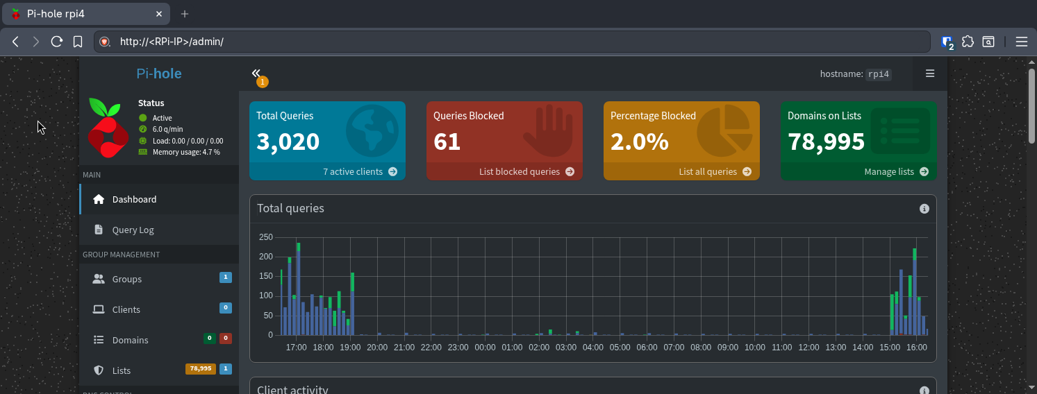
I use a Raspberry running Pi-hole as a DNS sinkhole (see this post), hence I want to let all of my hosts know they should use it for any DNS queries.
Pi-hole’s dashboard
To use the Pi-hole as DNS resolver:
Make the Raspberry Pi’s IP static, setting it to 192.168.20.2.
# Set the RPi's IP to be static, and 192.168.20.2/ip dhcp-server leasemake-static [findhost-name=rpi4]set[findhost-name=rpi4]address=192.168.20.2
Naturally, your Raspberry Pi – or whatever server of yours is running the Pi-hole service – should be on your homelab network before taking these steps.
You might need to reboot your newly-static host, so that it gets a new DHCP lease.
Allow LAN interfaces to ask the Pi-hole for DNS services.
# Add the newly-static-IP to an address-list, for cleaner firewall rule management/ip firewall address-listaddaddress=192.168.20.2comment="RPi4 running Pi-hole"list=RPi4
# Allow LAN interfaces to talk to the RPi4, only on the DNS port/ip firewall filteraddaction=accept chain=forward comment="LAN -> RPi4 (DNS via TCP): ACCEPT"dst-address-list=RPi4 dst-port=53in-interface-list=LAN protocol=tcp
addaction=accept chain=forward comment="LAN -> RPi4 (DNS via UDP): ACCEPT"dst-address-list=RPi4 dst-port=53in-interface-list=LAN protocol=udp
# Move these rules above the default-deny rulemove[find comment~"LAN -> RPi4"][findcomment="any -> any: DROP"]
Tell all VLANs’ DHCP servers to point to the Pi-hole.
# Update each DHCP server's handshake detail to have them point to the Pi-hole/ip dhcp-server networkset[finddns-server=192.168.10.1]dns-server=192.168.20.2set[finddns-server=192.168.20.1]dns-server=192.168.20.2set[finddns-server=192.168.30.1]dns-server=192.168.20.2set[finddns-server=192.168.40.1]dns-server=192.168.20.2
Disable the previously-created LAN -> router for DNS rule, as it’s no-longer needed.
# Disable the "LAN->router for DNS" rule/ip firewall filterdisable[findcomment="LAN -> router (DNS via TCP): ACCEPT"]disable[findcomment="LAN -> router (DNS via UDP): ACCEPT"]# Disable the router's DNS resolver -- for good measure/ip dnssetallow-remote-requests=no
Ensure it worked
Since we updated the DHCP’s handshake details we were using, we should unconnect-reconnect to the our main WiFi. That way, the DHCP server will give us the latest-DNS-settings, i.e. pointing-to-our-RPi.
Once reconnected, we should be able to load any internet page.
Redirect DNS packets to Pi-hole
Even with DHCP servers pointing to my Pi-hole, some devices – especially IoT hardware with hardcoded DNS settings – will attempt to bypass it by directly querying external servers like 8.8.8.8 or 1.1.1.1.
This is because the DHCP server’s DNS settings are merely a suggestion.
To enforce my ask-Pi-hole-for-DNS policy, I should intercept these DNS-queries-leaving-my-network and redirecting them to my Pi-hole (i.e. perform DNS hijacking). We can do so by adding NAT rules, allowing use to mess with packets before the leave our network.
What is NAT? And NAT rules
Network Address Translation (NAT) is a technique used by the router to map one IP address into another one. This is done by modifying the address information in the packet’s IP headers.
The main use for it is due to the IPv4 shortage. Using NAT, my ISP can give me one single public IP address, that my NAT will slap on all packets leaving my network, so that their source is the public IP. When a request’s response arrives, NAT will look at its internal connection tracking table, and put back that packet’s original destination IP.
Hence, NAT rules define how firewalls modify the source/destination IP of traffic passing through the NAT. Just like the other types of firewall rules, NAT has two chains, depending on the path taken by the packet, i.e.
srcnat (source NAT): Packets originating from a natted network.
dstnat (destination NAT): Packets going to a natted network.
To enfore our ask-Pi-hole-for-DNS policy:
Mangle all DNS packets that aren’t going to/from the RPi.
# Mark all DNS packet that aren't going to/from the RPi/ip firewall mangleaddaction=mark-packet chain=prerouting comment="LAN (!RPi) -> !RPi (UDP): MARK-PACKET"in-interface-list=LAN src-address-list=!RPi4 dst-address-list=!RPi4 dst-port=53protocol=udp new-packet-mark=dns-hijack passthrough=yesaddaction=mark-packet chain=prerouting comment="LAN (!RPi) -> !RPi (TCP): MARK-PACKET"in-interface-list=LAN src-address-list=!RPi4 dst-address-list=!RPi4 dst-port=53protocol=tcp new-packet-mark=dns-hijack passthrough=yes
Note that we let through DNS packets originating from our Pi-hole, and those destined for our Pi-hole, as otherwise we run into an infinite redirection.
How do we know they’re DNS packets?
We don’t really know for sure, but we flag all destination-is-port-53 packets as DNS packets.
Rewrite DNS packets going through the NAT.
# Rewrite the destination IP of DNS queries leaving the network/ip firewall nataddaction=dst-nat chain=dstnat comment="Redirect marked DNS packets to RPi4"packet-mark=dns-hijack to-addresses=192.168.20.2# Rewrite their source IP as well, so that the Pi-hole answers to the routeraddaction=masquerade chain=srcnat comment="Masquerade marked DNS packets"packet-mark=dns-hijack
We need to masquerade the source IP (i.e. replace it with the router’s IP) to avoid having the Pi-hole answer directly to the client.
That way, the Pi-hole will answer to the router, which will hijack the response and pass it on the client.
Since the packet’s path looks like a loop (client -> router -> pi-hole -> router -> client), this kind of NAT rule is called NAT hairpinning.
From the point of view of the client, it’s as if they had indeed queried their hardcoded DNS resolver; they will not know about our packet tempering.
Ensure it worked
To ensure it worked, try to load some URL – in your web browser – that you’ve never loaded before – to avoid any local cache hit.
If that works, you’re good to go.
Monitor Pi-hole with Netwatch
What if my Pi-hole goes down? Then my DHCP servers would tell its clients to use some dead device as their DNS server.
Hence, they wouldn’t be able to resolve any URL anymore.
To solve this, enters Netwatch – a MikroTik tool continuously monitoring the state of hosts on the network, running dedicated scripts when they go online/offline.
We can use Netwatch to monitor our Pi-hole’s availability, and have it update the DHCP server’s settings, firewall settings and NAT hairpin rule whenever it goes down/up.
To have Netwatch check whether the RPi is up or down, and toggle its use:
Create a netwatch instance pinging our RPi every minute.
# Create the netwatch instance/tool netwatchaddcomment="Toggle using the Pi-hole as DNS (DHCP + NAT hijack)"host=192.168.20.2interval=1m# Setup what happens when the Pi-hole goes down, i.e.:# 1. Enable using the router as a DNS resolver# 2. DHCP points to router's DNS resolver# 3. Disable NAT hairpin rules# 4. Allow DNS packets through the firewallset[findcomment="Toggle using the Pi-hole as DNS (DHCP + NAT hijack)"]down-script="/ip/dns set allow-remote-requests=yes/ip/dhcp-server/network set [find address=\"192.168.10.0/24\"] dns-server=192.168.10.1/ip/dhcp-server/network set [find address=\"192.168.20.0/24\"] dns-server=192.168.20.1/ip/dhcp-server/network set [find address=\"192.168.30.0/24\"] dns-server=192.168.30.1/ip/dhcp-server/network set [find address=\"192.168.40.0/24\"] dns-server=192.168.40.1/ip/firewall/nat disable [find packet-mark=\"dns-hijack\"]/ip/firewall/filter enable [find packet-mark=\"dns-packet\"]"# Setup what happens when the Pi-hole goes up, i.e.:# 1. Disable using the router as a DNS resolver# 2. DHCP points to RPi4# 3. Enable NAT hairpin rules# 4. Disallow DNS packets through the firewallset[findcomment="Toggle using the Pi-hole as DNS (DHCP + NAT hijack)"]up-script="/ip/dns set allow-remote-requests=no /ip/dhcp-server/network set [find address=\"192.168.10.0/24\"] dns-server=192.168.20.2 /ip/dhcp-server/network set [find address=\"192.168.20.0/24\"] dns-server=192.168.20.2 /ip/dhcp-server/network set [find address=\"192.168.30.0/24\"] dns-server=192.168.20.2 /ip/dhcp-server/network set [find address=\"192.168.40.0/24\"] dns-server=192.168.20.2 /ip/firewall/nat enable [find packet-mark=\"dns-hijack\"]/ip/firewall/filter disable [find packet-mark=\"dns-packet\"]"
Ensure it worked
To ensure it worked, shutdown your RPi4. Within 1min, your netwatch instance should notice it’s down.
Then, unconnect-reconnect to your network – to trigger a new DHCP handshake. You should then be able to browse the internet.
mDNS
I have some smart speakers that advertise their presence to other hosts on their network. Unfortunately, our VLANs break that.
If we’d like to know the IP of the host serving google.com (or any other website), we would ask the traditional DNS.
This is because someone registered – within the DNS – that google.com was the IP 74.125.29.100.
But what if we’d like to know the IP of the host serving some printing service on my network? Or some loud-speaker service? That’s where mDNS comes in.
What is mDNS?
Multicast DNS (mDNS) is a way for hosts on a local network to advertise services they can do to all other hosts on that network.
Let’s say I’m a printer, and I want to advertise my printing services to hosts on my network.
I will send a request – saying e.g. “Hi I can print stuff and my name is someprinter.local” – to a specific agreed-upon IP and port (i.e. IP 224.0.0.251 and port 5353)7, addressed to a specific agreed-upon interface (i.e. MAC address 01:00:5E:00:00:FB)8.
This shouting usually occurs at boot time, then every hour-ish, and on a clean shutdown.
That frame goes to the switch, which recognises this MAC address as a multicast MAC address.
As such, it broadcasts that frame to all interfaces in the source MAC’s broadcast domain.
Note that the IP and port aren’t relevant here, only the MAC address. We still need them because a valid request must have all OSI layers wrapped.
All interfaces then receive that frame, and learn that a printer is available – if they need one.
Now let’s say my computer ends up needing that printer. It will
Prepare an mDNS query addressed to the mDNS IP address, port and MAC address, asking for that printer’s IP
It sends that query through its local network interface – i.e. the active Ethernet port or WiFi chip.
The local switch picks up that frame, and sees the 01:00:5E:00:00:FB multicast MAC address. It hence broadcasts it out to all interfaces on the local network.
Most hosts will ignore that frame – seeing they’re not someprinter.local. The actual printer will recognize itself, and send a multicast response saying “I’m the printer and my IP is 192.168.30.234”.
Responding via multicast allows other hosts on the network to update their DNS cache.
My computer is now able to directly reach the printer, since it knows its IP.
Most mDNS shouting will come from my IoT VLAN – I’d expect – and I’d like people on the guest VLAN to be able to e.g. connect to my loud-speaker.
To enable mDNS:
Repeat mDNS shouts on the IoT and Guest VLANs.
# Have the router repeat the mDNS shouts to/from the IoT VLAN and Guest VLAN/ip dnssetmdns-repeat-ifaces=vlan40-guest,vlan30-iot
As described, mDNS shouts do not cross over the broadcast domain. Since IoT VLAN and Guest VLAN have their own broadcast domain, shouts coming from one domain won’t cross over to the other one. To address this, I create an mDNS repeater instructing my router to repeat all mDNS shouts from/to these interfaces.
Allow mDNS queries through the firewall when they’re from the IoT/Guest VLAN.
# Create an mDNS interface list for easier firewall rule management/interface listaddcomment="mDNS inferfaces"name=mDNS
/interface list memberaddinterface=vlan40-guest list=mDNS
addinterface=vlan30-iot list=mDNS
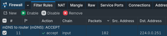
# Allow mDNS queries through the firewall/ip firewall filteraddaction=accept chain=input comment="mDNS -> router (mDNS): ACCEPT"dst-address=224.0.0.251dst-port=5353protocol=udp in-interface-list=mDNS
# Move that rule above the default "any -> router: DROP" rulemove[findcomment="mDNS -> router (mDNS): ACCEPT"][findcomment="any -> router: DROP"]
Our current firewall rules already allow Guest VLAN to send requests to IoT VLAN;
hence, once the Guest VLAN device knows where to find IoT VLAN device, we’re good to go.
Ensure it worked
In my case, I was now able to cast music to my loud-speakers from the Guest VLAN; that was all the check I needed.
Another good indicator it worked was seeing the amount of packets accepted by the firewall rules in WinBox.
A growing amount of packets accepted by our newly-added “accept mDNS shouts from these interfaces” rule
Avoid ISP hardware
ISPs usually sell/lease some hardware which is limited in capabilities with few setting choices.
To break away from that, I picked an ISP that allows me to used whichever hardware I choose.
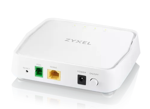
I’m in Switzerland on a fiber-optic link, meaning I have a socket in my living room – called an OTO port, a Swiss thing I think – with fiber optic ports. To convert that fiber optic signal into electric signal, I used an ONT, which I then connected to my router’s WAN port.
What is an ONT?
An Optical Network Terminal (ONT) is a device whose job is to convert fiber optic data into RJ45-friendly electric signals.
For my ISP to recognize my router and provide it with a public IP:
Tag all outgoing traffic with VLAN 10, as per my ISP’s instructions.
# Create a new VLAN 10 on ether1, as per my ISP's instructions/interface vlanaddinterface=ether1 name=vlan10-wan vlan-id=10# Add vlan10-wan to WAN/interface list memberaddinterface=vlan10-wan list=WAN
Use DHCP option 60, with value '10008,0001'.
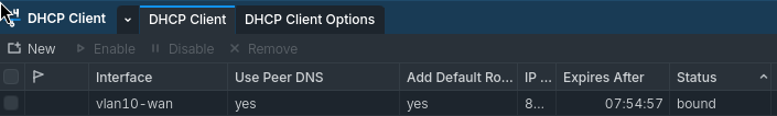
# Create DHCP option 60, as per my ISP's instructions/ip dhcp-client optionaddcode=60name=vendor-class-identifier value="'10008,0001'"# Apply it to my DHCP client/ip dhcp-clientadddhcp-options=hostname,clientid,vendor-class-identifier interface=vlan10-wan
At this point, your ISP should be providing your with a public IP. That can be checked on the IP > DHCP Client panel, i.e its status should be bound:
Remove the old config, as it’s no longer needed.
# Remove the now-unused DHCP client/ip dhcp-clientremove[findinterface=ether1]# Remove the now-unused ether1 from WAN/interface list memberremove[findinterface=ether1]
Tada ! Internet !
Ensure it worked
To make sure it worked, open any webpage. If it loads, you’re good to go.
That could be your wall plug, or some router-in-bridge-mode, or some fiber-link-to-ethernet-convert. More on that later. ↩
For each SSID, my router has to send out electromagnetic beacons through the air every 100ms, on each frequency. That’s how other devices can “know” about these ready-to-be-connected-to WiFi networks. But these beacons “crowd my airwaves”, i.e. take up available bandwiths. ↩
Why this specific IP and port you ask?
In the IPv4 world, some IP addresses – all within the 224.0.0.0 => 239.255.255.255 range – are reserved for one-to-many communications (i.e. multicast, as oppose to one-to-one communications – unicast). They are called multicast addresses.
Within this 224.0.0.0 => 239.255.255.255 range, 256 addresses – called the Local Network Control Block, i.e. 224.0.0.0 => 224.0.0.255 – are reserved for multicasting that should not be forwarded outside the local network. That is, all routers is instructed not to forward packets with that destination address.
Out of these, 224.0.0.251 ended up being picked as the mDNS IP address.
Regarding the port, since DNS uses port 53, mDNS uses port 5353. Computer scientists like to infuse sense in naming, even for ports. ↩
And why this specific MAC address you ask?
In the MAC addresses world, some are reserved for multicasting. That way, any switch receiving a frame with this destination MAC address knows they have to multicast it. And any interface receiving that frame knows they need to listen to it (even if it’s not their MAC address).